
Summary
- There is no single “right value”; kV/µA is a range that depends on the part, the powder and the target thickness.
- Starting point: flat surface 80–100 kV; deep corner/cavity 40–60 kV + low µA.
- Method: read the powder's TDS first, trial with a safe starting point, fine-tune by changing one variable at a time.
- Verify thickness with a micron gauge; check corners and back ionization by eye.
“How many kV should I use for powder coating?” is the most common question in the field. The short answer: there is no fixed number. The right kV and µA is a range that varies with the part's geometry, the powder's chemistry and the film thickness you are targeting. The good news is that you can narrow this range down confidently in a few steps.
Starting Values
Start every trial from a safe, middle point. Practical starting bands:
| Part type | kV | µA / current |
|---|---|---|
| Flat, wide surface (panel, cover) | 80–100 kV | Unrestricted / high |
| Mixed geometry (general work) | 60–80 kV | Medium |
| Deep corner / recess / cavity | 40–60 kV | Low (e.g. 10–30 µA) |
| Fine decorative / touch-up | 40–50 kV | Low |
These are starting points, not final values. Always read the powder's technical datasheet (TDS) first; the manufacturer gives the recommended kV and thickness range.
Step-by-Step Method
- Read the TDS: Start with the kV range and target microns recommended by the powder manufacturer.
- Verify grounding: Poor grounding (high resistance) ruins every setting; hanger-to-part resistance should ideally be below 1 MΩ.
- Safe start: Make a trial coat at 80–90 kV for flat surfaces and 50 kV for recessed parts.
- Change one variable: Don't change both kV and distance at the same time. If corners stay bare, lower µA first; if the surface is pitted/cratered, reduce kV and µA and increase the distance.
- Measure thickness: After curing, measure at several points with a micron gauge; check that it is within the target band and uniform.
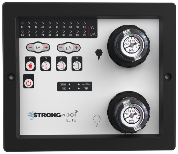
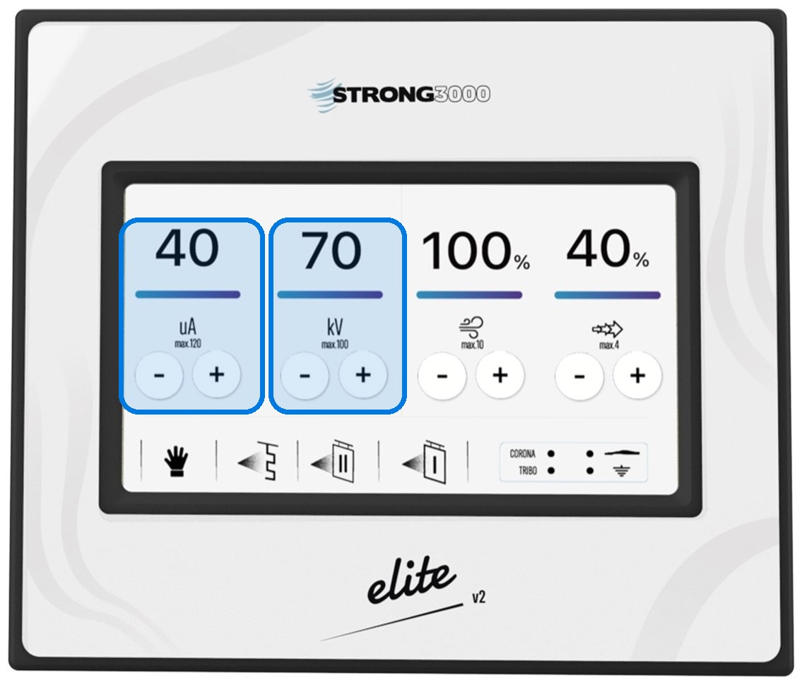
- Save the recipe: Store the working value as a recipe in the control unit; get the same result when the same part comes back.
Tip
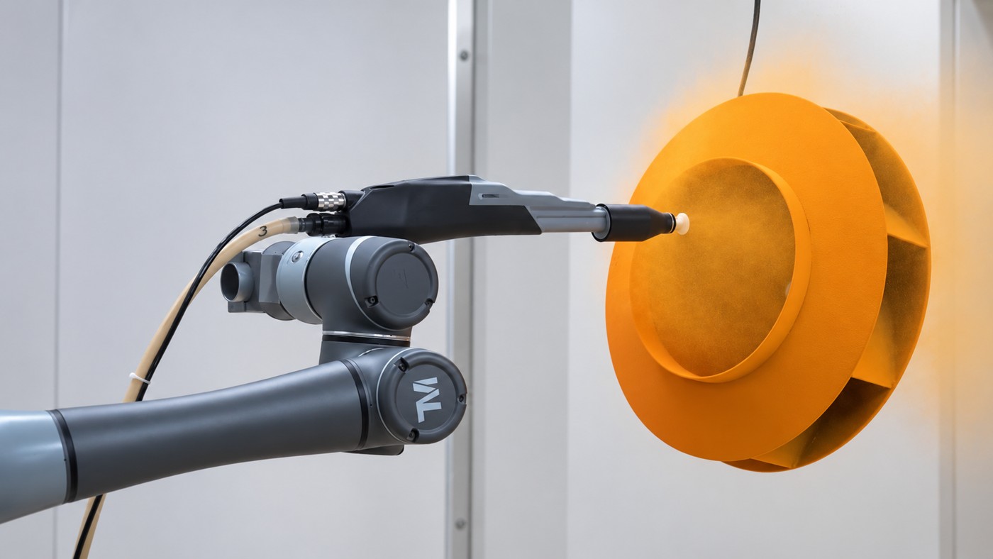
Holding the gun at 200–300 mm for the first coat lowers ion density and reduces back ionization. Distance is also a “setting”; it's not just kV/µA.
Common Mistakes
- Fixed high kV for every job: Leaving 100 kV on every part empties the corners and causes pitting.
- Ignoring µA: On many control units the current limit gets skipped; yet the key to corner penetration is often µA.
- Forgetting grounding: A painted/oxidized hanger renders even the best kV/µA setting useless.
- Estimating thickness by eye: Saying “it looked enough” without a micron gauge means waste and inconsistent thickness.
We covered why we look for the right value separately and the difference between kV and µA in the why setting kV and µA separately matters article.
Frequently Asked Questions
Typically 80–100 kV for flat, wide surfaces; for deep corners and recessed parts, 40–60 kV and low µA are preferred. The exact value is confirmed by the powder's technical datasheet (TDS) and field trials.
On flat surfaces the current can be left unrestricted; in recesses and corners low µA (e.g. 10–30 µA) is used to prevent back ionization. The right value is found with a trial coat.
No. Beyond a certain point, excess ions repel new particles and limit thickness; they also cause craters through back ionization. Thickness is a balance of kV, µA, distance and gun motion.