
In Short
- The Faraday cage effect is the inability of charged powder particles to reach corners, recesses and concave areas; electric field lines concentrate on the outer surface.
- The first step is to lower kV and µA; dropping from 60–100 kV to 40–60 kV noticeably improves recess fill on most enclosures.
- Tribo guns, robots and intelligent motion application increase recess penetration by reducing free ion charge and distance errors.
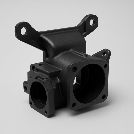
When coating the inside corner of an electrical enclosure, no matter how close you bring the gun, the bottom of that narrow recess stays thin or does not cover at all. The metal is properly grounded, powder flow is steady, and the outer surfaces are covered flawlessly. The problem is not the powder; it lies in the relationship between the part's geometry and the electrostatic field. This behavior is called the Faraday cage effect, and it is one of the most stubborn problems anyone coating narrow profiles, wire mesh, channels and deep recesses faces in powder coating.
What Is the Faraday Cage Effect
A corona gun charges powder particles with high voltage (typically 60–100 kV) and creates an electric field toward the grounded part. Charged particles follow these field lines to the surface. Here is the problem: electric field lines always head for the most protruding, sharpest points of a conductive surface. A corner, an edge or a protrusion gathers the field onto itself; a recessed cavity or an inside corner where two walls meet becomes a “shadow” zone in terms of the field.
It takes its name from Michael Faraday's cage experiment. Inside a closed conductive shell, the electric field is close to zero. Even if the part being coated is not a complete cage, a deep recess behaves by the same logic: field lines pile up at the mouth and edges of the recess and barely reach the bottom. A charged particle goes not where it wants to, but where the field pulls it. The result: too much film on the outer surface, too little in the inside corner.
The second layer of the problem is free ions. While corona charging charges the powder, it also produces a large number of free ions in the air. These ions accumulate inside the recess and create a “counter-charge” cloud on the part. This accumulated charge repels the charged particles that arrive later; the bottom of the recess effectively closes itself off to powder. This can be accompanied by back ionization: in the overcharged zone the powder craters and its texture deteriorates.
Where and How It Appears
The effect is most pronounced on these parts:
- Electrical enclosure bodies: inside corners and mounting pockets stay thin.
- Narrow U and C profiles: the inner face of the profile is covered less than the outer face.
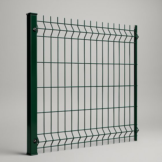
- Wire mesh, grilles, baskets: wire intersections and inner surfaces are weak.
- Radiator sections, heat exchangers: powder does not get between the sections.
- Boxes and housings: corner weld seams and concave transitions.
Be careful when diagnosing the symptom: missing coverage in an inside corner is not always Faraday. Poor grounding, a clogged nozzle, wrong powder flow or gun angle can produce similar results. The tell-tale sign of Faraday is this: the outer surfaces and protrusions take too much powder (with thickness even rising excessively) while only the inward-facing areas stay bare. In other words, the problem is not powder reaching the part, but powder distributing wrongly on the part.
First Step: Lowering kV and µA
It feels counterintuitive, but the way to get more powder into a recess is usually to lower the voltage. High kV makes field lines even harsher at the outer protrusions and increases free ion production. When you lower kV, the field softens, the particle's own kinetic energy (being carried by air) becomes more dominant, and the powder can be carried mechanically into the recess.
In practice you turn down two values together: output voltage (kV) and current limit (µA). Current limiting suppresses ion flow as the gun approaches the part; this reduces back ionization and counter-charge buildup in the recess. On modern guns, the “deep recess / Faraday” preset is usually a low kV + low µA combination.
| Part type | Starting kV | Note |
|---|---|---|
| Flat surface, large panel | 80–100 kV | High transfer efficiency, wrap-around |
| Body with shallow recesses | 50–70 kV | Balanced coverage |
| Deep recess, inside corner | 40–60 kV | Soften the field, limit the current |
| Wire mesh, grilles | 30–50 kV | Low kV + short distance |
Tip
Do not pull values to the extremes in one go. Lower kV in steps of 10, coat a test part, cure it and check inside-corner thickness with a magnetic gauge (DFT). As the recess starts to fill, powder pickup on the outer surface also drops somewhat; find the right balance for the part by measurement. Exact values are confirmed by the powder manufacturer's technical datasheet (TDS) and field measurements.
Tribo, Robots and Intelligent Motion
Voltage adjustment solves most jobs, but for deep geometries there are hardware options too. Changing the charging method comes first. A tribo (triboelectric) gun charges the powder by friction rather than high voltage; there is no strong corona field producing free ions. The problem of field lines cutting off the recess largely disappears, the particle moves more with its own conveying air and enters the recess more easily. The price of tribo is lower charging efficiency and the requirement that the powder be tribo-compatible; not every powder charges well tribostatically.
The second axis is motion and distance. In manual coating, holding the gun at an angle into the recess, going to the bottom first and then the edges, and keeping the distance in the 15–25 cm band make a difference. But the human hand is not repeatable; the inside corner of the same enclosure is not coated for the same time and at the same angle every time. This is where automatic and robotic application come in. Aligning the gun with the recess axis and moving it at constant speed, constant distance and constant angle defeats the Faraday effect mechanically rather than electrostatically: the powder is carried to the bottom not by the field but by a correctly directed airflow.
The intelligent motion gun approach combines these two ideas. Motion-controlled systems such as the OWL Intelligent Motion Gun programmatically adjust the gun's trajectory, speed and trigger timing to the part geometry; they slow down in recessed areas and speed up on flat surfaces. This gives the inside corner enough dwell time while preventing excessive thickness and orange peel on the outer surface. The ability of electrostatic parameters (kV/µA) to change in sync with motion allows different recipes for different zones on a single part.
Caution
Trying to solve the Faraday problem with “more powder” or “higher kV” usually backfires: excessive thickness on the outer surface, back ionization and a cratered texture at the recess mouth result, and the bottom still stays bare. First soften the field (lower kV/µA), then improve the mechanical transport of the powder (distance, angle, motion).
Application Strategy
A sequence that works in the field goes like this. First verify grounding; part-to-hanger resistance should generally be below 1 megohm. Poor grounding creates a coverage problem that looks like Faraday but is fundamentally different. If grounding is sound, proceed in order:
- Bottom first, then outside: coat recesses and inside corners first at low kV, leaving the outer surfaces for later. If the outer surface charges early, the resulting charge closes the mouth of the recess even further.
- Keep the distance: 15–25 cm. Getting too close causes local back ionization; moving too far away causes transfer losses.
- Go in at an angle: align the gun with the recess axis, pointing into the recess rather than perpendicular to the surface.
- Adjust the airflow: slightly increasing conveying air when coating recesses pushes particles mechanically to the bottom, but too much blows off freshly applied powder.
- Two stages if needed: deep areas at low kV, followed by outer surfaces at normal kV.
To understand the charging physics as a whole, it helps to review how electrostatic powder coating works; the concepts of kV, µA and wrap-around explain why Faraday fixes work. Making the geometry coatable from the start is also part of the solution: increasing corner radii in design, opening unnecessarily deep pockets with vent/drain holes and softening sharp inside corners ease the burden on electrostatic settings. Rather than expecting the line to compensate for an uncoatable geometry, designing the part to be coatable is the most lasting solution.
In short, the Faraday cage effect is not a material defect but an inevitable interaction between the electric field and geometry. The right approach is not to ignore it but to manage it: soften the field, carry the powder mechanically, make the motion repeatable and, if possible, design the geometry to be coatable from the start.
Frequently Asked Questions
First soften the field lines by lowering kV and µA, then carry the powder mechanically into the recess with gun distance, angle and airflow. In deep geometries, a tribo gun or intelligent motion/robotic application makes a marked difference.
High kV makes the electric field harsher at outer corners and increases free ion production; this leads to charge buildup and back ionization at the recess mouth. Low kV softens the field and lets the powder enter the recess with its own conveying air.
Yes. Tribo charges the powder by friction instead of high voltage and does not produce a strong corona field or free ions; that is why particles enter recesses more easily. The price is lower charging efficiency and the requirement that the powder be tribo-compatible.